- What am I talking about?
- Resolution is important
- Effect of binning
- Focus is important
- Light condition
- IMU as a source of angles
- Magnets: strikes back
- Game of parameters
- Conclusion
What am I talking about?
If your robot will move in the conditions, where a using of GPS is almost impossible, e.g. inside the buildings or the enclosures, you need to have a spare source of a pose estimation. One of the cheap and proven solution is the pose estimation with a calibrated camera and the printed markers, like AprilTags or ArUco markers. The second type of markers (ArUco) we are using in our project. And it takes some time, but after a long journey with the different experiments, now we have 5-10 centimeters precision with a distance of 6-7 meters. With this precision we’ve also reached a quite acceptable framerate, about 50 fps.
I’ve decided to mention in this article several important notes, that I’ve got, while developed this system of visual positioning. All of this notes related to OpenCV 3.4. All benchmarks has been made on ODROID-XU4 and using oCam-1MGN-U Plus.
Resolution is important
It’s quite obvious, that a time consumption of the marker detection algorithm depends on a count of pixels of processing image. If you have 1280x720 pixels image, every time the algorithm will process 3 times more, than if it was 640x480. But if you want to decrease the resolution in order to get a performance, the precision will decrease accordingly. (Actually, I didn’t found the real complexity and time consumption of aruco::detectMarkers and cv::solvePnP, but a short glance on the source code of this algorithms shown that a time scales with a size of an image. Also I’ve checked it on the real experiments.)
oCam-1MGN-U Plus camera can provide 60fps@1280×720 and 80fps@640×480, and when I changed the resolution I’ve noticed, that time to take an image from camera matrix to my program through the v4l driver changes too. The changes were not too big, about several milliseconds, but if we are speaking about robot positioning, we need to get as fast system as possible with an acceptable precision.
Effect of binning
The camera matrix sensor has physically a fixed resolution and it’s equal to maximal image resolution. Usually you can see it counted in megapixels, for example the mentioned oCam’s sensor has 1280 x 960 / 1000000 and approximately equal to 1.2 MP.
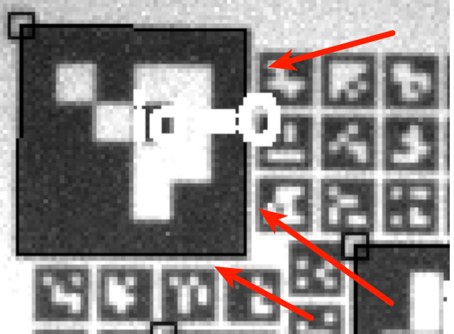
The question is how the camera can provide the image with smaller size? Here is no magic, it calls binning. Long story short, an image processor inside the camera takes several pixels of raw image and make just one pixel from them. In my case, for 640x480 we have 4 –> 1 pixel transformation. Why is it important? Because the neighboring pixels start to affect each other. If we have some markers close to each other, on the some shoots we can have the incorrectly detected marker’s contours. To mitigate it, try to do not put markers close to each other.
How this effect does look like:
Focus is important
As you can understand from the text above, the visibility of marker’s contours have a significant impact. So, before doing anything, be sure that your camera is focused on an acceptable distance.
Light condition
When I’ve debugged the problem with the pose estimation, I was surprised how an output of the adaptive thresholding strongly depends on illumination of a marker’s board. We’ve used infrared projectors DOMINANT II™+ Infra Red as a source of light, but it wasn’t enough. This projectors produces very uneven illumination, and picture becoming over-lighted in a center and darker to the borders. That leads to the problem, that white color becoming gray and the algorithm of markers detection starts to output noisy.
Just remember, that you need to provide as even light as possible.
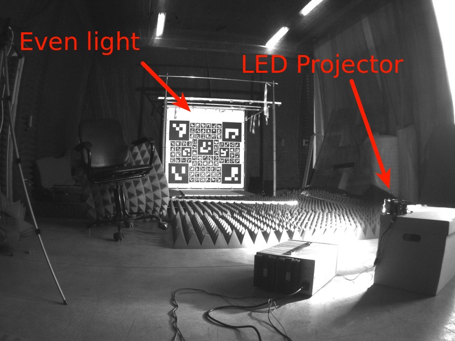
For example, it’s the experimental installation. Here is used Stratus 100W LED module. It’s difficult to use this module in our case, but it’s a good example of even light: all parts of board is lit up. Black color is black, white is white.
IMU as a source of angles
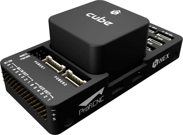
The IMU of our flight controller can gives a very precise value of rotation quaternion.
But wait, the output of solvePnP is the rotation and the translation vectors. What if we’ll use the rotation angles from IMU, but the translation from solvePnP? Actually, the estimations of the translation vector by solvePnP is more precise, than rotation, that means if we will use more accurate source of rotation angles, we will get better working system. Additionally, we can use a smaller resolution of an image, enough to estimate the translation fairly, and score in the performance.
To be clear, we’ve used the pose.orientation from /local_position/pose topic, and then converted it to Euler angles (it’s easy to deal with and more understandable for humans). After it, you can make the tf2::Transform and use it everywhere you want in your ROS code.
We’ve tested this solution and it works really well: very precise positioning without severe deviations. Just what we want, but…
Magnets: strikes back
In my previous article I’ve mentioned that one day we’ve discovered a very hard magnetic interference inside our automated ground station. Yes, that breaks all our plans, because since this moment we can use the yaw angle from IMU. Is it a time to return to the Stone Age or we can do something to make our visual position estimation robust and precise again?
Game of parameters
That was a time, when I took my laptop and went to our laboratory to find a solution. We didn’t want to use a bigger resolution due to it hurts the performance, but we had to fix the accuracy.
I’ve started to rereading a documentation and looking on our algorithm. We had two players: aruco::detectMarkers and cv::solvePnP. It didn’t take too much time to find, that cv::solvePnP is doing it’s job quite well, but aruco::detectMarkers is not. Because of binning, illumination and focus, it was difficult for detectMarkers to recognize contours of markers. I’ve found that this method has lots of parameters and I didn’t want to choose it manually. Also with several experiments I’ve noticed, that most important parameters is:
adaptiveThreshWinSizeMaxadaptiveThreshWinSizeMinadaptiveThreshWinSizeStepcornerRefinementMethodcornerRefinementWinSizecornerRefinementMinAccuracy
Too many parameters to find with brute force, unfortunately. But we can use the same value for adaptiveThreshWinSizeMax and adaptiveThreshWinSizeMin, because we just want to find the best window. That means that we can rid of adaptiveThreshWinSizeStep. We also can set a small value for cornerRefinementMinAccuracy and after check it’s effect visually. The value of cornerRefinementMethod was also chosen as CORNER_REFINE_CONTOUR because it was more stable than CORNER_REFINE_NONE and CORNER_REFINE_SUBPIX.
So, after this inspection left only two mutable parameters: adaptiveThreshWinSize and cornerRefinementWinSize.
I wrote the small piece of code, that went through the parameters, sent it to another service, that calculated standard deviation and combined it to acsv file. After I’ve put the camera on a fixed place, turned on the light and went out to do something else. After several hours the report was done.
Here is two of several reports, that I’ve created. I’m not so good in math, so I just took a standard deviation of position and yaw angle, normalized it (unfortunately, you can’t just sum degrees with meters) and looked on a top 10.
Long story short, I’ve chosen this values: adaptiveThreshWinSizeMin=5, adaptiveThreshWinSizeMax=5, adaptiveThreshWinSizeStep=100, cornerRefinementWinSize=10, cornerRefinementMinAccuracy=0.001, cornerRefinementMaxIterations=50. I’m not sure, that it’s a best one, but the tests in a real world show, that it works quite well and better than it was.
Conclusion
After long journey I found different conditions, that affects the quality of visual based position estimation. Light, camera properties, algorithm parameters, IMU and magnets can play it’s role on this scene. Maybe I haven’t discovered any important things, that can flip the game, but I had to timebox my investigation and in the end of it, we get well working system.